Installation plan
Before you begin
Check whether:
- The device is not bent or damaged.
- Housing, cabling and all connectors are not damaged.
Set up an installation plan before beginning the installation. Based on the users' needs and capabilities, this plan should take into account:
- Where which part of the device should be placed.
- How the device will be operated.
- A robust and reliable positioning. Hard or sudden movements of the wheelchair may not disorganize the installation.
Step 1: motor unit
- How will you place the motor unit?
- Left or right?
- Horizontal or vertical movement?
- Horizontal placement:
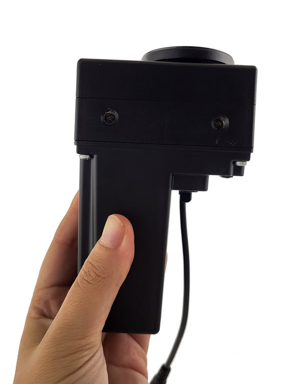 Note: This is the best position to have visibility of the motor unit for the attendant or installer.
 - Vertical placement:
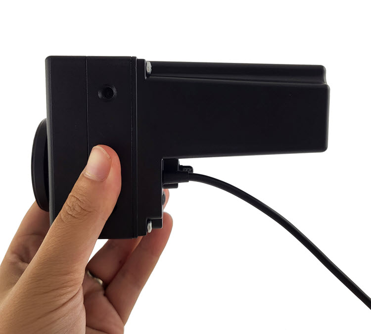
- Horizontal placement:
- How far should the arm open?
Note: Mount the Multi Swing 2G motor unit in such a way that the jacks are protected as much as possible from water entering. - Once you have decided how you want to place the motor unit, connect it to the wheelchair via part A1. Connect a normally open button (e.g. mo-vis Twister) to the red jack of the motor unit. Also connect the motor unit to the configurator (see Defining parameter settings). Adjust the following parameters if necessary: Open angle and Mounting (see Parameter settings for more information).
- Move the arm to its end stop. A first push on the button connected to the red jack will close the arm as long as you press the button or until it has reached its end stop. A second push on the button will open t he arm as long as you press the button or until it has reached its maximum open angle. Before proceeding to the next step, make sure that the arm is at its end stop.Note: This is a very important step, as the arm is most stable at its end stop. If you carry on with the mounting without paying attention to the end stop, the result of your installation will be less stable.
Step 2: Multi Swing Adapter Set
The Multi Swing 2G Adapter Set is used to connect the Multi Swing 2G arm to the Multi Swing 2G motor unit.
Step 3: Arm Assembly
The M031-Arm Assembly is composed of several elements, which have to be put together
- Remove the plastic cable covers.
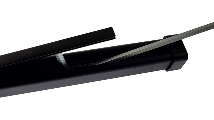
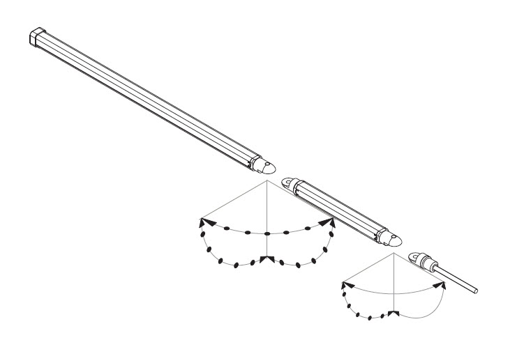
- Connect the two parts to each other.
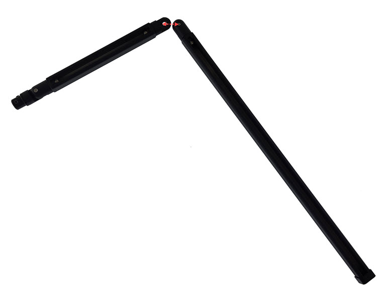
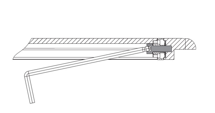
- Adjust the angle of the Multi Swing 2G arm by loosening the bolt on the inside of the
extrusion part. Both joints can be moved in steps of 15°.
Step 4: Preliminary fitting
Now, you can slide part B into part C. Don't forget to use part C1 at this point, to make sure that the Arm is tight inside the Adapter and that you can tighten it further without causing damage. Locate the pushplate between the Arm and the Adapter on the side of the setscrews. The setscrews should fall in the slots of the pushplate. Align the pushplate with the side of the Adapter.
Check visually how you will place the arm for the end-user.