Preparations
- Please check the packaging and verify that all items are included.
- Make sure that you have all the necessary documentation and knowledge to install this device.
- Check the condition of the device.
Qualified service engineer
Only a qualified service engineer may install the device.
Installation plan
Set up an installation plan before beginning the installation. Based on the users' needs and capabilities, this plan should take into account:
- Where which part of the device should be placed.
- How the device will be operated.
- A robust and reliable positioning. Hard or sudden movements of the wheelchair may not disorganize the installation.
The Multi Switch should not be used in conditions where the malfunctioning of the device can cause potential risk situations.
The device contains a controller that continuously checks the integrity of the device: whenever a problem is detected, the device will be switched off automatically. When this happens, check the fault flash code or use the configurator to check why the device stopped.
Input of the Multi Switch

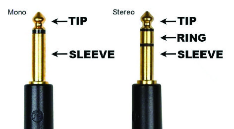
- Mechanical switch with mono jack 3.5 mm: switch connected between tip and sleeve; ring is continuously connected to sleeve.
- mo-vis proximity sensors: No force or clicking is required. Compared to a mechanical switch, there is an increased comfort for the user and increased ability to control the device and outputs. The sensitivity of both sensors is fully adjustable with the mo-vis Configurator Software. Tip is the sensing input, ring is the shield, sleeve is open. The mo-vis proximity sensors are based on the principle of capacitive sensing. They are capable of measuring conductive objects (e.g. a finger or a metal stick) that approaches the sensor. The bigger the surface of the sensor, the more sensitive it will be (so the 24 mm version is the most sensitive one). The sensor is most sensitive at the front side in the centre. At the sides, it is only slightly sensitive and on the bottom it is immune.
 CAUTION: Moisture (e.g. rain) is also a conductive substance. A few drops of rain will not cause issues, but a water film can cause the sensor to be activated all the time.Note: A test finger was used to determine the distance vs. the sensitivity parameter setting. Know that this is not an exact relationship and sensitivity may vary depending on the size/shape of the finger.
Sensitivity Distance 24 mm (in mm) Distance 12 mm (in mm) 100% 10.00 3.00 90% 8.5 2 80% 7.00 1.25 70% 5.00 0.50 60% 3.00 0.20 50% 2.00 0.10 40% 1.50 0.05 30% 1.00 <0.05 20% 0.50 <0.05 10% 0.25 <0.05 5% 0.05 <0.05 Note: In case high sensitivities are used (>70%), make sure the sensor is well fixed and the cables are well routed. Moving the sensor/cable can have an influence on the sensitivity or even produce false contacts.
Output of the Multi Switch
The outputs are potential free and fully isolated from the rest of the Multi Switch.
| Output | Location |
|---|---|
| 1 | Green tip |
| 2 | Green ring |
| 3 | Yellow tip |
| 4 | Yellow ring |
Multi Switch box
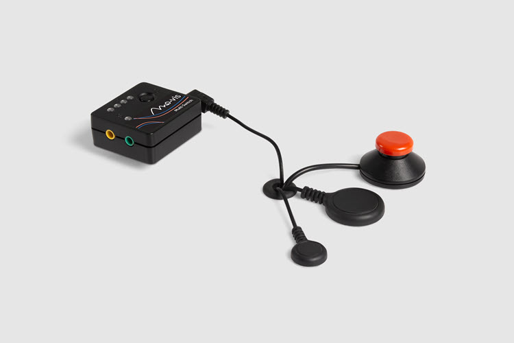
- Output LEDs: four green LEDs on the front of the Multi Switch indicate which output is selected. It makes it easier for the user to select the desired channel.
- Status LED: A separate green LED at the front indicates the device status:
Status LED Active Short on, long off Fault Number of flashes, long off (see Error codes) - Push button: At the front of the Multi Switch, a push button is provided. To learn more about the function of this button, see Parameter settings and parameter Calibration Method).
- USB connection: The Multi Switch is equipped with an isolated micro USB connection at the right side.
- Parameter configuration: Use this connection to connect the Multi Switch to a PC to interact with the mo-vis Configurator Software and set all the parameters of the in- and outputs.
- Power supply: When the Multi Switch is connected to a USB power source (e.g. USB Charger, power bank, laptop, tablet...), the device will be powered and operational.
The Multi Switch only requires a minimal amount of energy. Most standard power sources are not designed to deliver minimal current over a longer period of time. Contact mo-vis for more information and assistance on choosing the right power source for the Multi Switch.
CAUTION: ground loop risk. Both the USB port and the input jack are connected to ground. Make sure not to introduce a ground loop by connecting the USB port and the input jack to different circuits, both supplied from the same battery. A ground loop can cause a ground current flowing from one circuit to the other over the Multi Switch. If the ground current is too high, the Multi Switch will not work properly or can even be overstressed. This can lead to permanent damage to the Multi Switch. A good solution is to use and isolated USB power supply.