R-net Joystick Connection
Purpose
An R-net joystick has a communication cable with an R-net connector. The cable can be directly plugged into the R-net electronics of the wheelchair. The joystick then controls the wheelchair in all its functions (driving, electric gears …).
For more information about the R-net system, please refer to the Curtiss-Wright website http://www.cw-industrialgroup.com
Connecting the R-net communication cable
To connect the communication cables, insert the connector into its mate and push firmly.
The connector is inserted correctly if the yellow pins are completely invisible. The connectors are secured using a friction system.
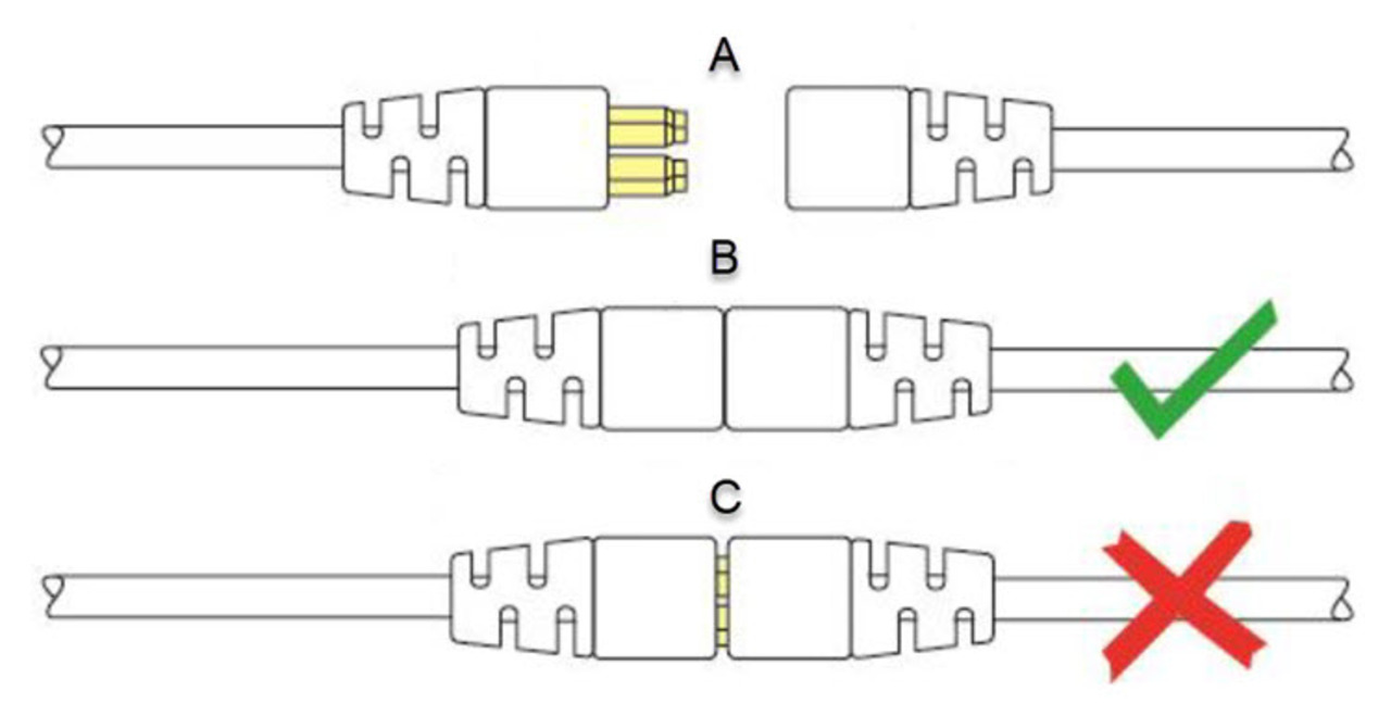
- A
- not connected
- B
- correctly connected
- C
- incorrectly connected
R-net parameters
Some R-net parameters need to be set for correct usage of the mo-vis R-net joysticks. For this we refer to the Curtiss-Wright manual SK77981-14 | R-net Technical Manual | Chapter 3 - Progamming
- In most cases, this parameter needs to be set to Universal for all mo-vis joysticks.
- In combination with certain other devices (e.g. Scoot Control), it is advised to set this parameter to JSM. Please refer to the Installation manual of the other devices for more information.Note: If you have several input devices of the same type, please refer to the Curtiss-Wright manual SK77981-14 | R-net Technical Manual | Chapter 3 - Programming to install as Input Device Subtype.
R-net (Ch. 3 - 7.5): : the default setting of this parameter is Profiles. If you want access to the modes for control of other wheelchair functionalities, such as seating positions, etc., then you have to select Profiles/Modes.
LED status
The illumination of the LED on the joystick interface indicates the operational status of the joystick.
| R-net status | Tilt parameter | Joystick tilted | LED status |
|---|---|---|---|
| Out of focus | X | X | LED flashes as heartbeat |
| In focus | Enabled | N | LED on |
| In focus | Enabled | Y | LED flashes as heartbeat |
| In focus | Disabled | Y | LED on |
| In focus | Disabled | N | LED on |
| Configuring | X | X | LED flashes fast |
| Power cycle | X | X | LED flashes as heartbeat |
| Error | X | X | Flash the error code |
Error codes
When a fault occurs, the LED of the mo-vis Joystick will start to flash. A long delay is followed by a number of flashes with a short delay. The error message depends on the connection type. Count the number of flashes and look up the according error message in the table below:
| Flash count | Reason | Required action |
|---|---|---|
| 1 | - | - |
| 2 | Connection cable/driver issues | Check/replace cable to wheelchair, and / or check / replace sensor cable (if available), or replace PCB |
| 3 | Power supply | Check cable and/or replace PCB |
| 4 | Joystick/sensor fault | Check/replace joystick |
| 5 | - | - |
| 6 | ADC - internal Analog to Digital converter | Replace PCB |
| 7 | Test flag failed or Diagnostic failed | Redo tests and/or replace PCB |
| 8 | CPU fault | Replace PCB |
| 9 | Scheduler fault | Update software or replace PCB |
| 10 | Coding error | Update software or replace PCB |
R-net trip codes
When a fault is detected by the device, an R-net trip code will be generated. The trip code will be shown on the joystick (if it is present and equipped with a graphic display). The trip code will also be logged in the R-net system and can be investigated using the R-net PC Programmer.
If you want to learn more about trip codes, see the Curtiss-Wright manual | SK77981-14 R-net Technical Manual.
Fault log
A fault log with counters is maintained. The fault log can be accessed by the configurator (dealer level). Below is an overview of registered faults.
| Fault | Reason | Required action |
|---|---|---|
| CPU error RAM | CPU consistency check failed | Replace PCB |
| CPU error FLASH | ||
| CPU error EEPROM | ||
| Run error scheduler | Firmware consistency check failed | Update Software or replace PCB |
| Code error framework | ||
| Code error application | ||
| MSP command corrupt | Corrupt command was received | Connection with the PC went wrong, try again |
| MSP command unknown | Unknown command was received | Connection with the PC went wrong. Update firmware (contact mo-vis) or update the Configurator Software. Try again. |
| MSP sub command unknown | Unknown sub command was received | |
| MSP argument invalid | Invalid argument received | |
| MSP device not ready | Device was not ready to receive an MSP command | Connection with the PC went wrong. Update firmware (contact mo-vis) or update the Configurator Software. Try again. |
| MSP device wrong state | The device is not able to receive a command in the current device | |
| PCB test failed | Factory test failed | Contact mo-vis |
| Assembly test failed | ||
| Field test failed | Field test failed (calibration) | |
| Test flag check | One or more test flags not set | Redo tests and/or contact mo-vis |
| ADC | ADC conversion error | Check R-net cable, replace PCB interface |
| R-net Uart overflow | Uart send queue is full | Replace PCB |
| R-net Uart Underflow | Uart receive queue is empty | |
| R-net Communication timeout | Maximum number of packet retransmissions is reached | Replace PCB |
| R-net Tx overflow | Packet transmit buffer is full | |
| R-net Rx overflow | Packet receive buffer is full | Replace PCB |
| R-net invalid seq nr | Received a packet with an invalid sequence number | |
| R-net data packet error | Data packet ACK mismatch | Replace PCB |
| R-net data descr error | Invalid packet data descriptor | |
| R-net Api version error | The R-net chip contains an invalid API version | Load the latest API version into the R-net chipset with the R-net dongle |
| R-net chip tripped error | The R-net chipset has encountered an internal error |
Internal chipset error: Replace PCB R-net system error: solve R-net system error |
| Communication | Communication with the sensor (joystick) failed | Check cable to sensor and/or replace sensor (only authorized dealers) or contact mo-vis |
| Sensor (joystick) | The sensor (joystick) is faulty | |
| Accelerometer | The accelerometer fails | Replace PCB interface |
Supported R-net parameters
The following R-net parameters of the wheelchair electronics may or may not be supported by the mo-vis joysticks.
| Parameter | Supported | Firmware version |
|---|---|---|
| Global parameter | ||
| Momentary screens enabled | N | |
| Change profile while driving | N | |
| Change speed while driving | N | |
| Actuator switches while driving | N | |
| Speed adjust | N | |
| Profile button | Y | V02.00 |
| Actuator endstop beep | N | |
| Sounder volume | Y | V02.03 |
| Start-up beep | N | |
| Lock function enabled | N | |
| Reverse driving alarm | Y | V02.00 |
| Emergency stop switch | N | |
| OBP keycode entry | N | |
| Power-up mode | N | |
| External profile jack function | N | |
| Profile / mode jack detect | N | |
| On / off jack detect | N | |
| Profiled parameter | ||
| Joystick forward throw | Y | V02.01 |
| Joystick reverse throw | Y | V02.01 |
| Joystick left throw | Y | V02.01 |
| Joystick right throw | Y | V02.01 |
| Joystick deadband | N Note: Use dead band setting in the mo-vis configurator |
|
| Invert left/right JS axis | Y | V02.01 |
| Invert fw/rev JS axis | Y | V02.01 |
| Swap joystick axis | N Note: Use rotate function in the mo-vis configurator |
|
| Change mode while driving | Y | V02.00 |
| Sleep timer | Y | V02.00 |
| Standby timer | Y | V02.00 |
| Switch to standby | Y | V02.01 |
| Mode selection in standby | Y | V02.01 |
| Standby in modes | Y | V02.01 |
| Standby forward | Y | V02.00 |
| Standby reverse | Y | V02.00 |
| Standby left | Y | V02.00 |
| Standby right | Y | V02.00 |
| Remote selection | Y | V02.03 |
| Background | N | |