Installation
Heavy Duty Kit for R-net Standard Joystick (M002-24)
- Disassemble the R-net joystick
Step Action Example 1 Remove the screws at the back of the joystick. 
2 Release the top half of the housing. If present, carefully release the locking system of the connector. 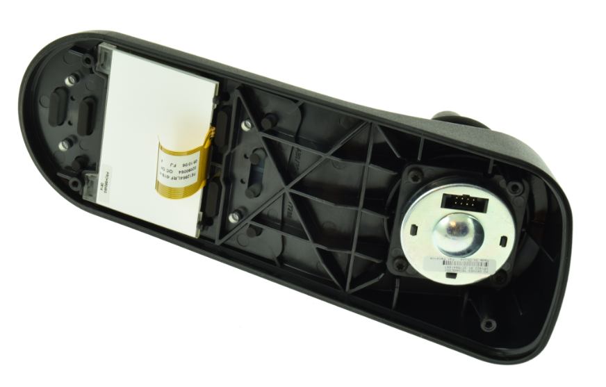
3 Remove the joystick sensor. 
- Modify the joystick sensor
Step Action Example 1 Remove the original spring of the joystick. If necessary, cut away the plastic retainer. 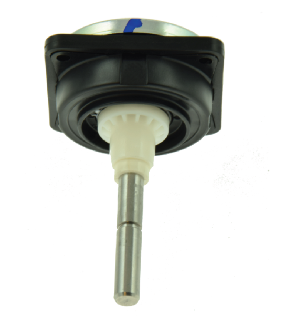
2 Place the new spring, slide washer bush and circlips. 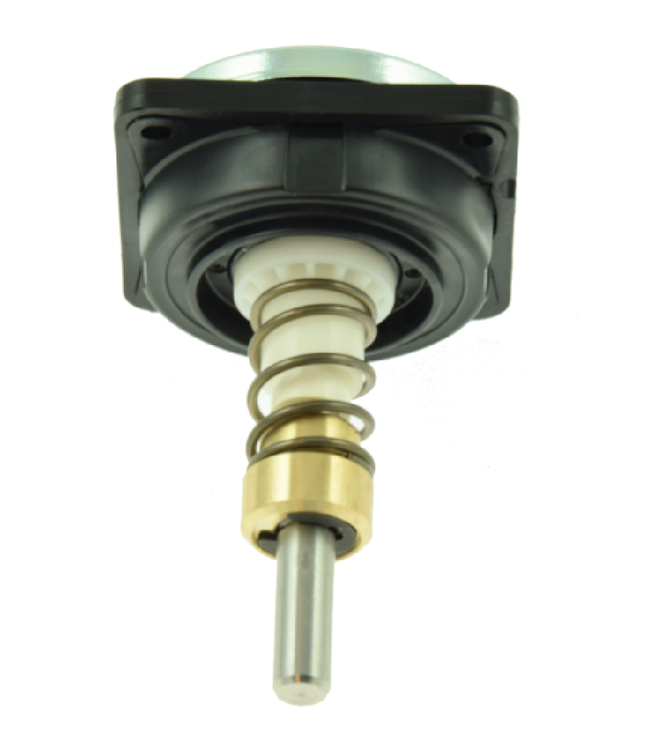
- Assemble the joystick
Step Action Example 1 Locate the 4 mounting tubes at the back of the joystick sensor top cover. 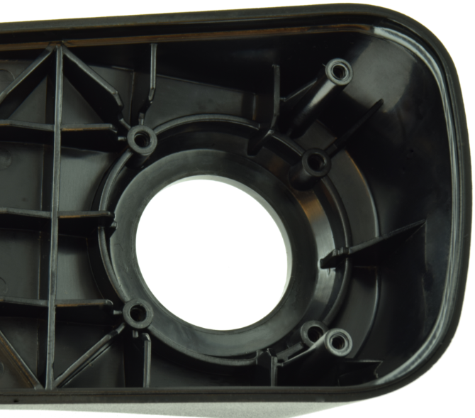
2 Use a drill of 3 mm to open the mounting tubes in the top cover. 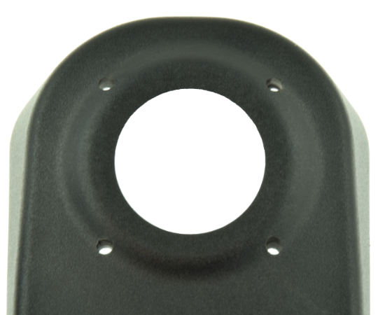
3 Gently remove the reinforcement plate, screws and washers of the upper part of the heavy duty kit. 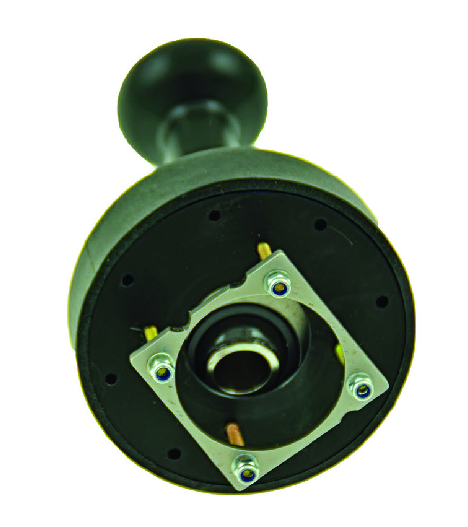
4 Assemble the joystick sensor, washer and screws. Apply ample grease to the sliding bush, spring and top of the joystick axle. 
5 Screw the parts together. Make sure all screws are evenly tightened. To tighten the screws: use a star-pattern sequence. 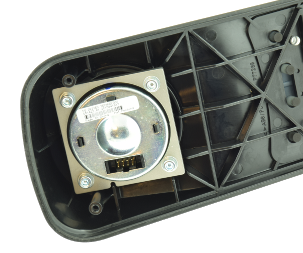
6 Check the joystick movements. If the joystick is blocked or gets stuck, the 4 screws may be tightened too much. Release the screws a little and recheck. 
7 Mount the back cover. Check visually if the assembly is done correctly (for example, are the gaskets located correctly?). 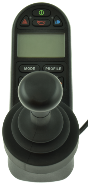
8
Heavy Duty Kit for CJSM2 (M002-44)
- Disassemble the R-net joystick
Step Action Example 1 Remove the screws at the back of the joystick. 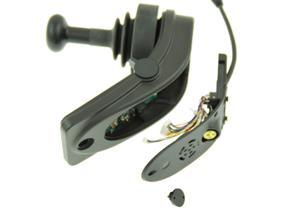
2 Release the top half of the housing. If present, carefully release the locking system of the connector. 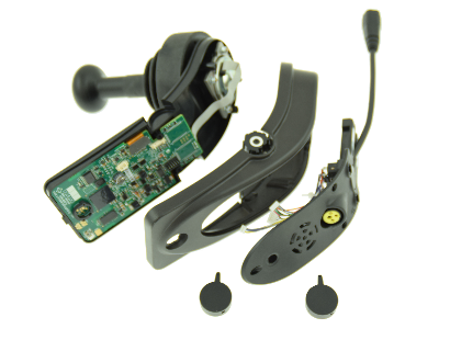
3 Remove the joystick sensor.
- Modify the joystick sensor
Step Action Example 1 Remove the original spring of the joystick. If necessary, cut away the plastic retainer.
2 Place the new spring, slide washer bush and circlips.
- Assemble the joystick
Step Action Example 1 Locate the 4 mounting tubes at the back of the joystick sensor top cover. 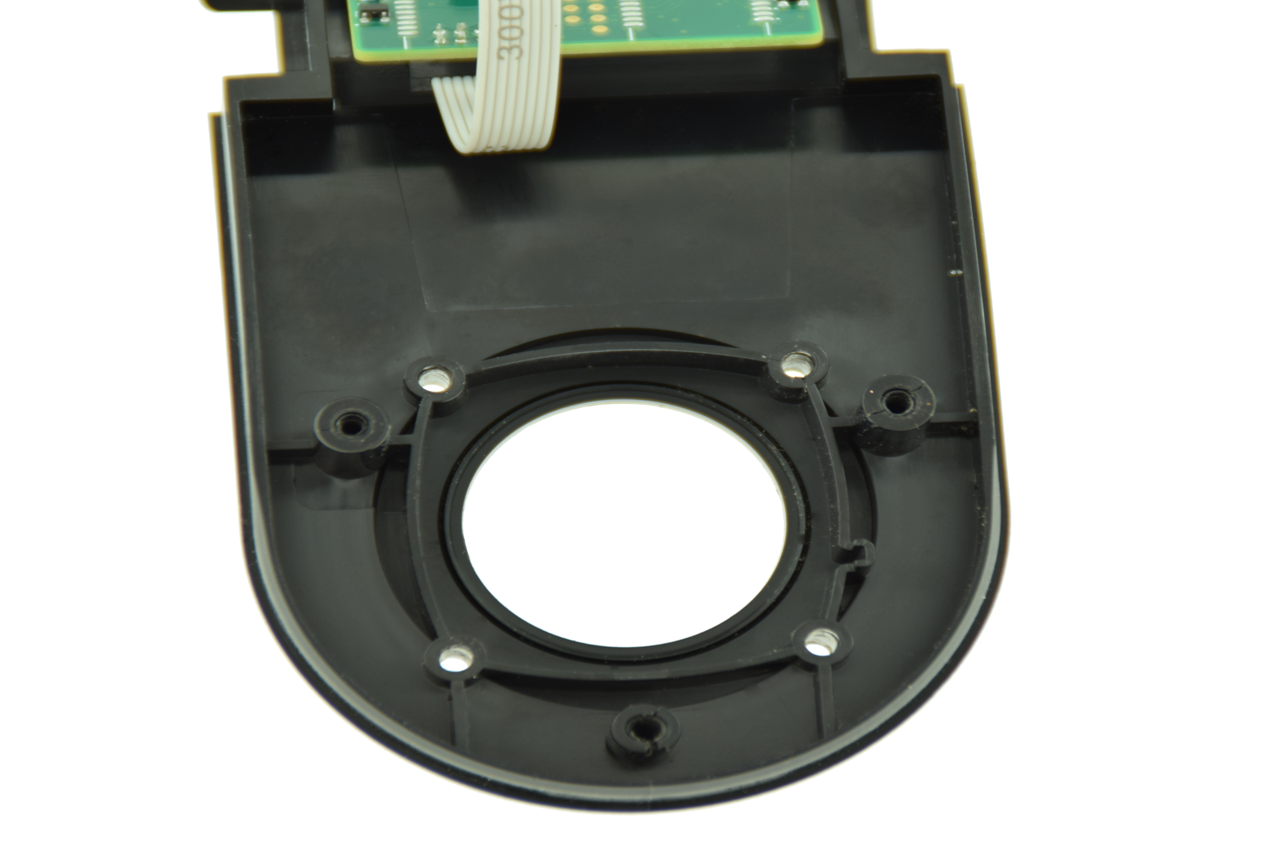
2 Use a drill of 3 mm to open the mounting tubes in the top cover. 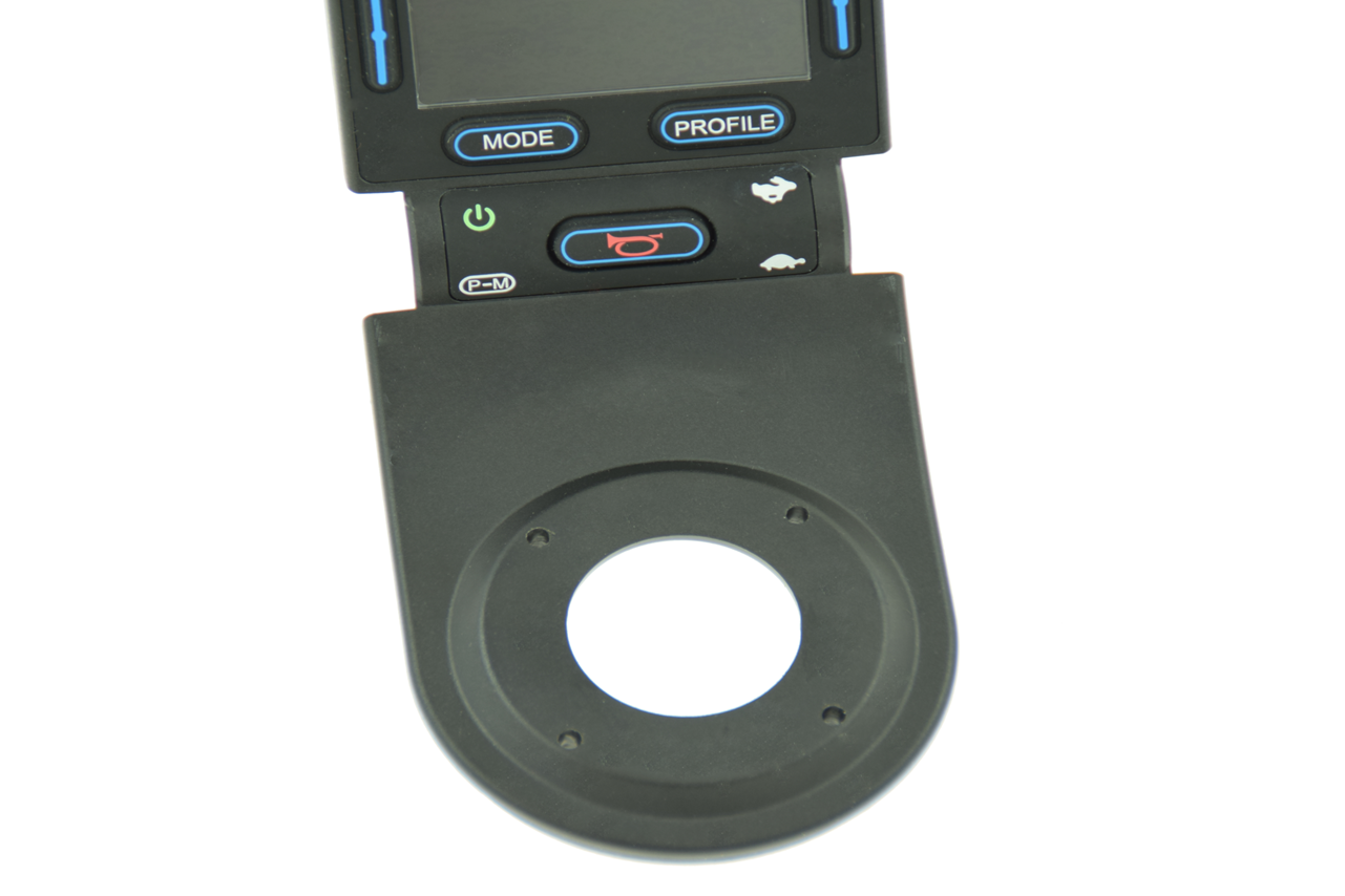
3 Gently remove the reinforcement plate, screws and washers of the upper part of the heavy duty kit.
4 Assemble the joystick sensor, washer and screws. Apply ample grease to the sliding bush, spring and top of the joystick axle. 
5 Screw the parts together. Make sure all screws are evenly tightened. To tighten the screws: use a star-pattern sequence. 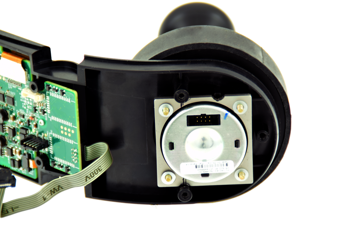
6 Check the joystick movements. If the joystick is blocked or gets stuck, the 4 screws may be tightened too much. Release the screws a little and recheck. Mount the back cover. Check visually if the assembly is done correctly (for example, are the gaskets located correctly?). 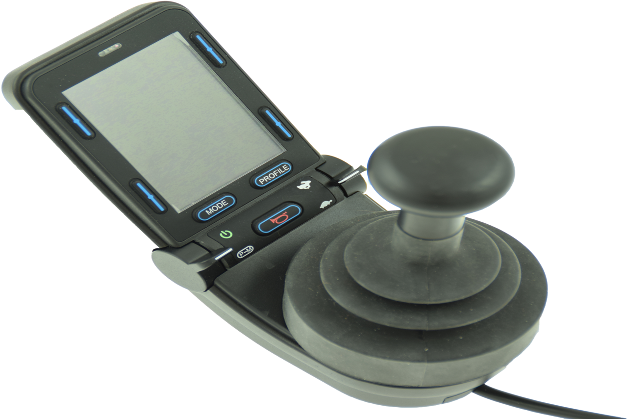
Heavy Duty Kit for Curtis Standard Joystick (M002-40)
- Disassemble the Curtis joystick
Step Action Example 1 Remove the screws at the back of the joystick. Release the top half of the housing. 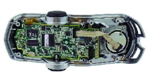
2 If present, carefully release the locking system of the connector. 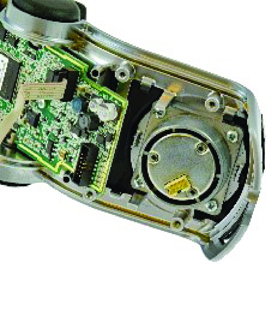
3 Remove the joystick sensor. 
- Modify the joystick sensor
Step Action Example 1 Remove the original spring of the joystick. 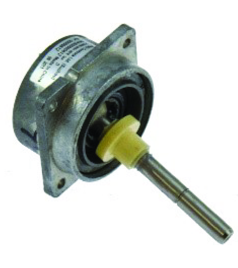
2 Place the spring fill ring, new spring, slide washer bush and circlips. 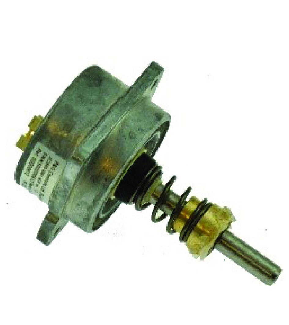
- Assemble the joystick
Step Action Example 1 Locate the 4 mounting holes at the back of the joystick sensor top cover. 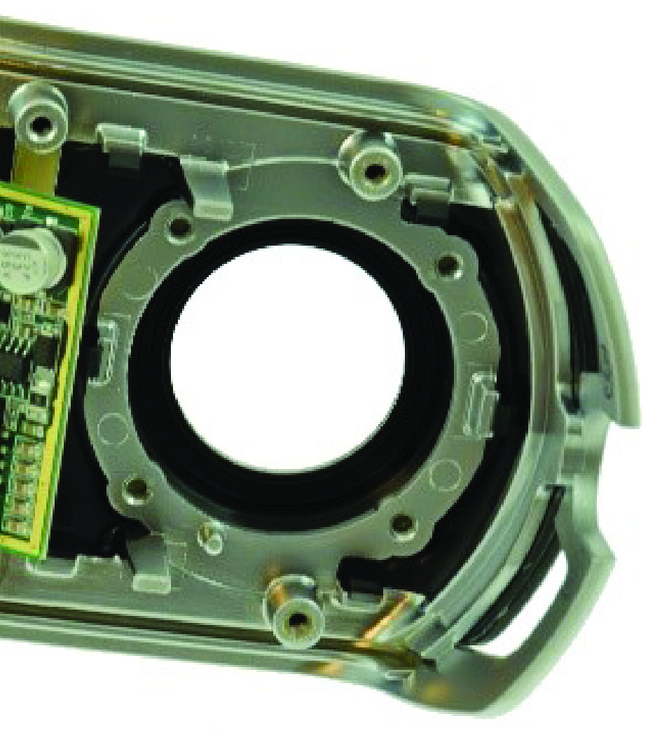
2 Use a drill of 3 mm to open the mounting tubes in the top cover. 
3 Gently remove the reinforcement plate, screws and washers of the upper part of the heavy duty kit.
4 Assemble the joystick sensor, washer and screws. Apply ample grease to the sliding bush, spring and top of the joystick axle. 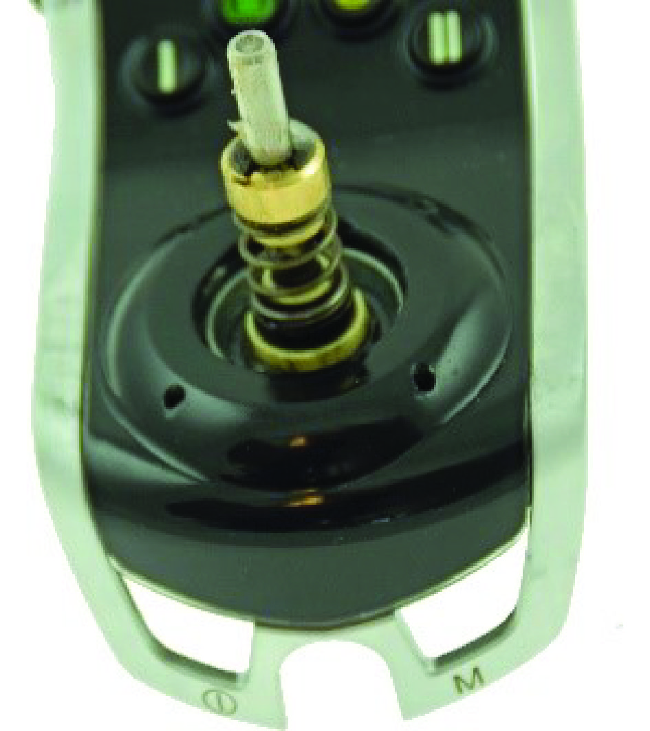
5 Screw the parts together. Make sure all screws are evenly tightened. To tighten the screws: use a star-pattern sequence. 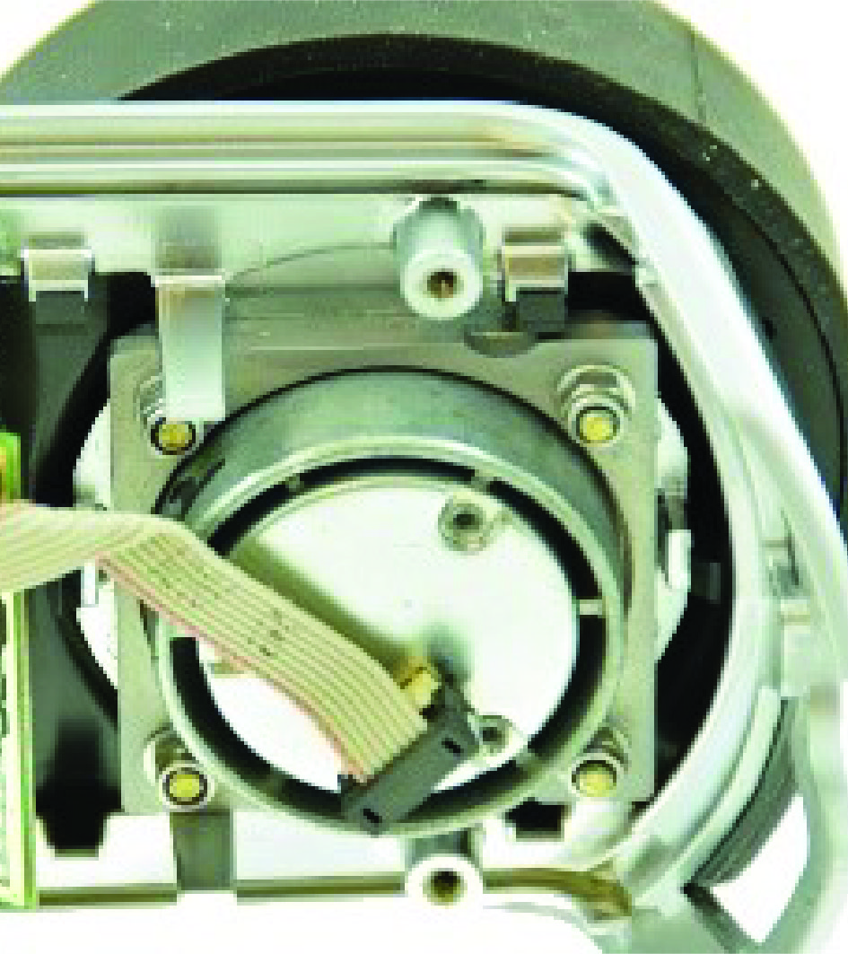
6 Check the joystick movements. If the joystick is blocked or gets stuck, the 4 screws may be tightened too much. Release the screws a little and recheck. Mount the back cover. Check visually if the assembly is done correctly (for example, are the gaskets located correctly?). 