Heavy Duty Joystick Installation
Changing the joystick tip
If required, the joystick's tip may be replaced by a custom tip (for example a 'T'.
To remove the default joystick tip, open the rubber cover below the joystick from the bottom towards the top and use a M12*1.5 wrench to unscrew the tip.
Note: Replacing the joystick tip is not advised and should only be done after careful consideration and at your own risk. Contact mo-vis for more information.
Installing the Heavy Duty Joystick
- Define the position of the joystick. When the USB connection points towards the user, a forward movement of the joystick will result in an according forward movement of the wheelchair. If needed, you can change this position in steps of 90° with the Configurator Software.
- Mount the unit with the two included M6*12 bolts at the desired location. If you use the Heavy Duty Mounting Ring Assembly, see Heavy Duty Mounting Ring Assembly. CAUTION: Do not mount the unit using the screw holes at the bottom of the unit.
- Place and secure all cabling on the power chair.
- Place a power on/off (pwr) and/or mode (in) switch, secure their cabling and insert their connections.CAUTION: Before inserting a connector, remove the protective cover. If the connections are not used, always put or keep the protective covers in.CAUTION: This is Class I Medical Device (MDR 2017/745). All accessories, including switches, must also comply with the MDR 2017/745 regulations (e.g. the mo-vis Twister, tested according to EN12184 standards).
- Connect the cabling to the wheelchair electronics.CAUTION: All wheelchair electronics must be switched off during installation.
Heavy Duty Mounting Ring Assembly
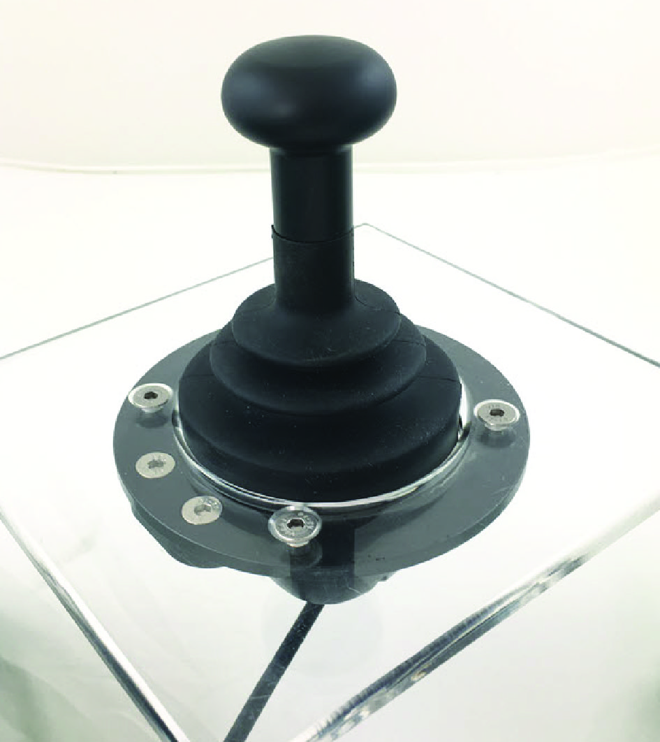
When mounting the Heavy Duty Joystick in a flat surface (for example tray or table top), you can use the Heavy Duty Mounting Ring Assembly (M002-28) to secure the joystick directly to the surface.
CAUTION: Tighten the screws firmly, but not excessively. Excessive force may damage the unit.