Installation
CAUTION: Before you start with the installation:
- Please check the packaging and verify that all items are included.
- Make sure that you have all the necessary documentation and knowledge to install this device.
- Check the condition of the device.
Installation Plan
Set up an installation plan before beginning the installation. Based on the users' needs and capabilities, this plan should take into account:
- Where which part of the device should be placed.
- How the device will be operated.
- A robust and reliable positioning. Hard or sudden movements of the wheelchair may not disorganize the installation.
Warning: Protect the device against bumps. Mind damaging the unit and wiring. Make sure that cabling is mounted in such a way that excessive wear and tear is avoided.
Warning: Make sure that loose parts of the cable are out of reach to avoid strangulation or other injuries.
CAUTION: Long periods of repetitive motion using the product may be associated with nerve, tendon or muscle injury in your hands, wrists, arms, shoulders, neck or back. See a qualified health professional for pain, numbness, weakness, swelling, burning, cramping or stiffness.
CAUTION: Do not pull or wrap the cable around the device.
Installation
- Define the position of the device. Make sure that it is easily accessible to the user.
- The device should be mounted on a flat surface. It should be mounted securely with consideration for minimal risk of jamming or blocking (access to) the device.Note: Use the delivered screws for surfaces with a thickness of up to 2 mm. If you use a thicker surface, be aware that the depth of the insert is 3 mm max.
- The connector jack should stay clean and needs to be inserted completely into the device.
Adjusting the dip switch
Adjust the dip switch by following these steps:
- Disconnect the switch.
- Remove the rubber insert on the bottom of the device.
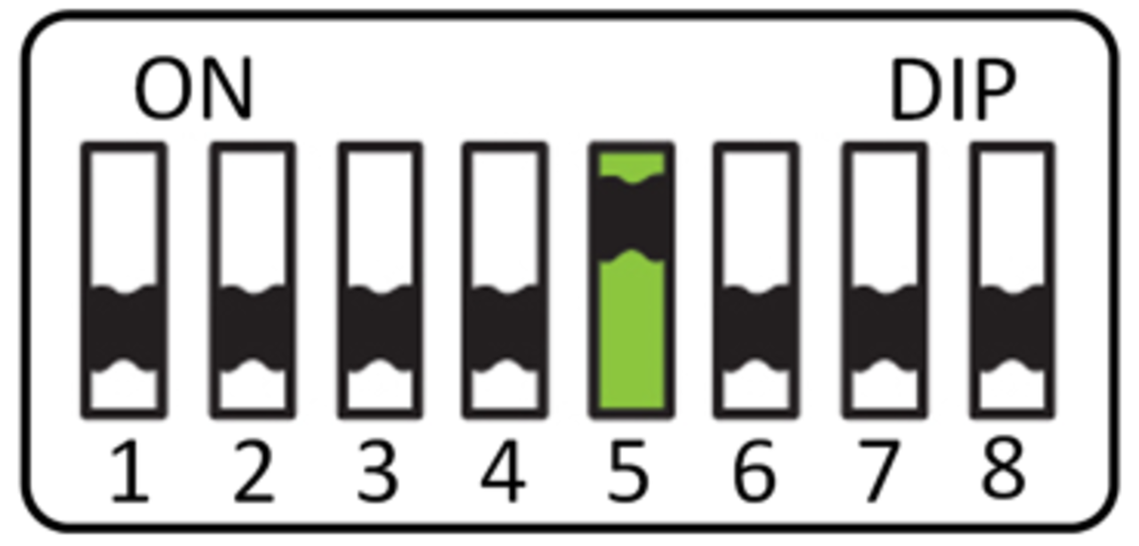
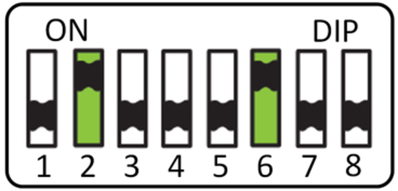
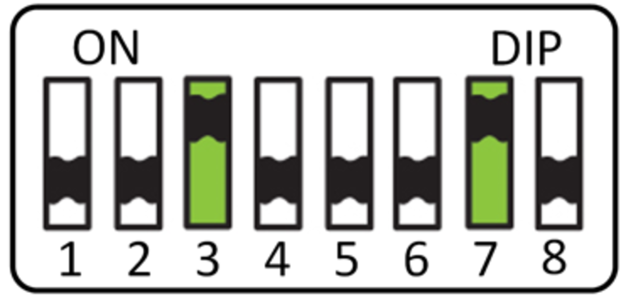
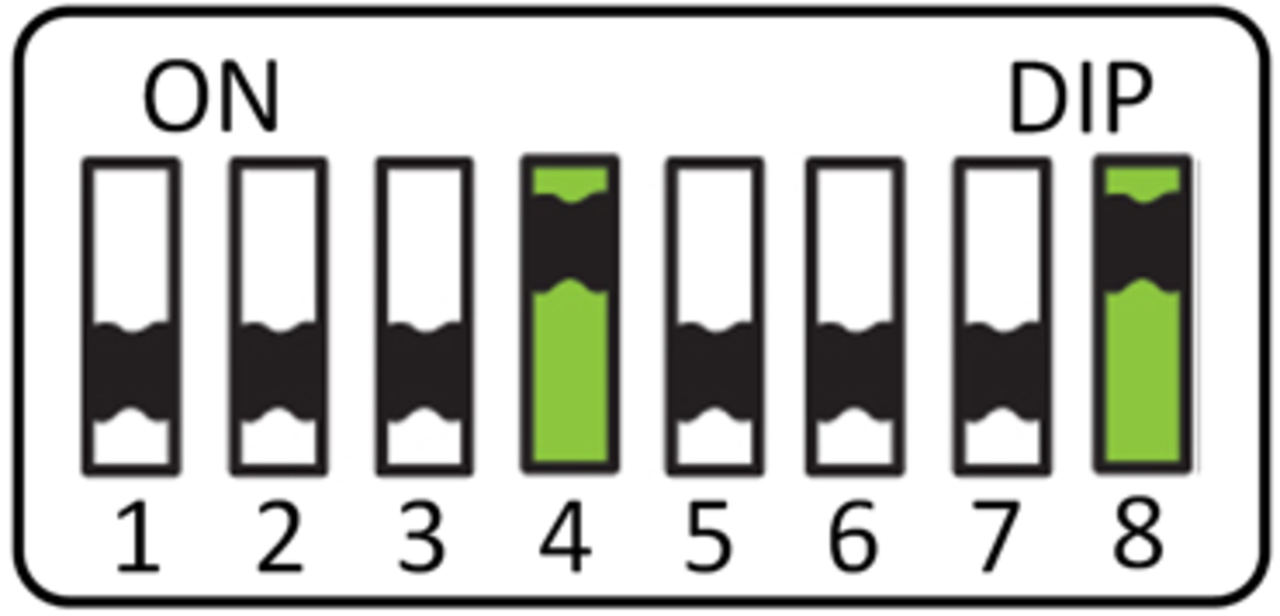
- Configure the dip switch by using a small screwdriver (see positions below).
- Reapply the rubber insert.CAUTION: If the rubber insert is not fitted correctly or even at all, this can compromise the waterproofness of the device.
Position Functionality 
Default position: compatible with default systems which require a normally open connection. 
R-net resistor values: Compatible with Curtiss-Wright specifications for the CJSM II and Omni II. 
LiNX Band 10 resistor value 
LiNX Band 1 resistor value - You can now reconnect and use the device.
Note: Some R-net and LiNX parameters need to be set correctly before the safety switch functionality is operational. See .