Multi Joystick Installation
-
Define the position of the joystick.
When the jack connections are at the right hand side, a forward movement of the joystick will result in an according forward movement of the wheelchair. If needed, you can change this position in steps of 90° with the Configurator Software.
- Determine which of the three slots you will use to guide the cable.
-
Secure the mounting plate with the four screws to the base of the joystick housing.
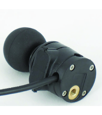
CAUTION: Tighten the screws firmly, but not excessively. Excessive force may damage the unit. -
Place the Q2M half clamp at the bottom of the unit. Use an Allen wrench to mount the 14 mm bolt.
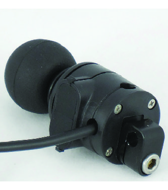
Note: It is not advised, but you may mount the joystick without using the Q2M half clamp. -
Slide the unit over a Q2M rod, or any other 6 mm rod, to position the Multi Joystick on the wheelchair.
A Q2M Rod D6 50 mm is included in your package, but you can use any other Q2M Rod (e.g. a C- or S-Rod from the Multi Swing).
-
Place and secure the interface unit and all cabling on the wheelchair.
Warning: Place the Interface unit with the connectors facing downwards. This is to prevent water from entering the Interface unit.
-
Place a power on/off (pwr) and/or mode (in) switch, secure their cabling and insert their connections. You can use the connections on the Interface unit.
CAUTION: Before inserting a connector, remove the protective cover. If the connections are not used, always put or keep the protective covers in.CAUTION: This is Class I Medical Device (MDR 2017/745). All accessories, including switches, must also comply with the MDR 2017/745 regulations (e.g. the mo-vis Twister, tested according to EN12184 standards).Note: Do not use the connections on the joystick and interface unit at the same time.
-
Connect the cabling to the wheelchair electronics.
CAUTION: All wheelchair electronics must be switched off during installation.