All-round Joystick (Light) Installation
CAUTION: Tighten the screws firmly, but not excessively. Excessive force may damage the unit.
All-round Joystick table mounting set

When mounting the All-round Joystick (Light) on a flat surface (e.g. a table), use the M002-25 All-round Joystick table mounting set.
Alternatively, you can insert 4 M4 bolts (not included in the package) through the surface to secure the All-round Joystick (Light) directly on the surface
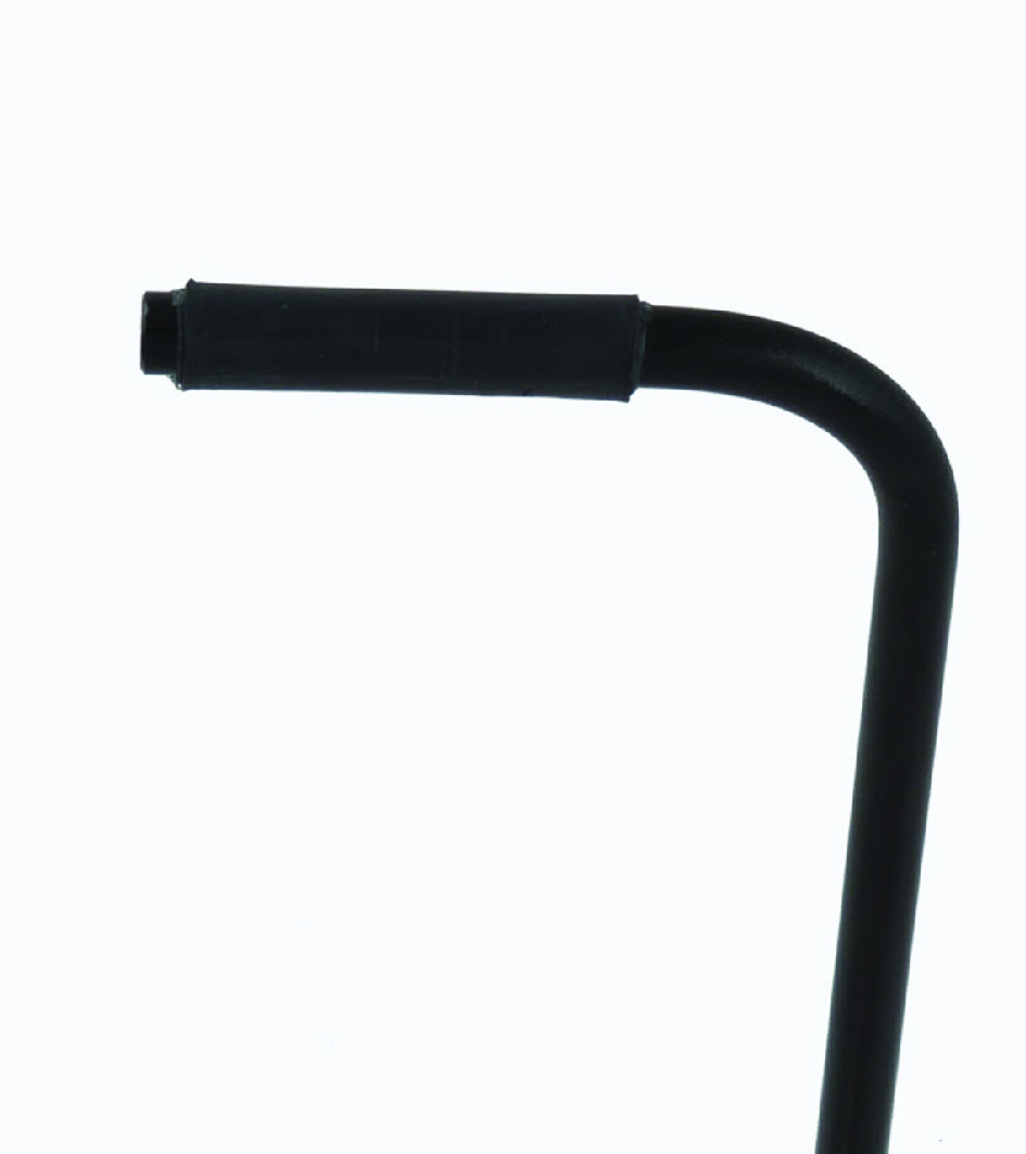
Satellite Twister
You can mount on or two Satellite Twisters to the All-round Joystick (Light):
| Description | Picture |
|---|---|
| Define the location of the Satellite Twister: left, right or on both sides. | |
| Unscrew and remove the cover for the Satellite Twister connection with a screwdriver. |
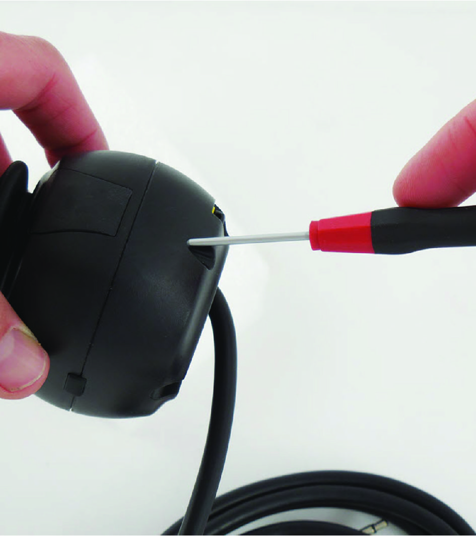
|
| Place the Satellite Twister firmly into the open slot. | |
| Use the screw of the cover to secure the Satellite Twister to the All-round Joystick (Light). |
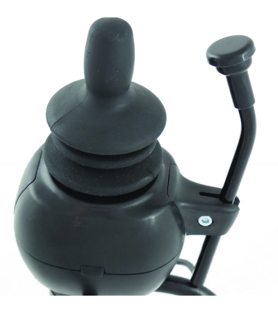
|
| If required, place a second Satellite Twister in the same way. | |
| Connect the cabling of the Satellite Twister to the All-round Joystick (Light). | |
All-round Joystick mounting set installation
| Description | Picture |
|---|---|
| Define the position of the joystick. When the USB connection points towards the user, a forward movement of the joystick will result in an according forward movement of the wheelchair. If needed, you can change this position in steps of 90° with the Configurator Software. | |
| Determine which of the two slots you will use to guide the cable. |
|
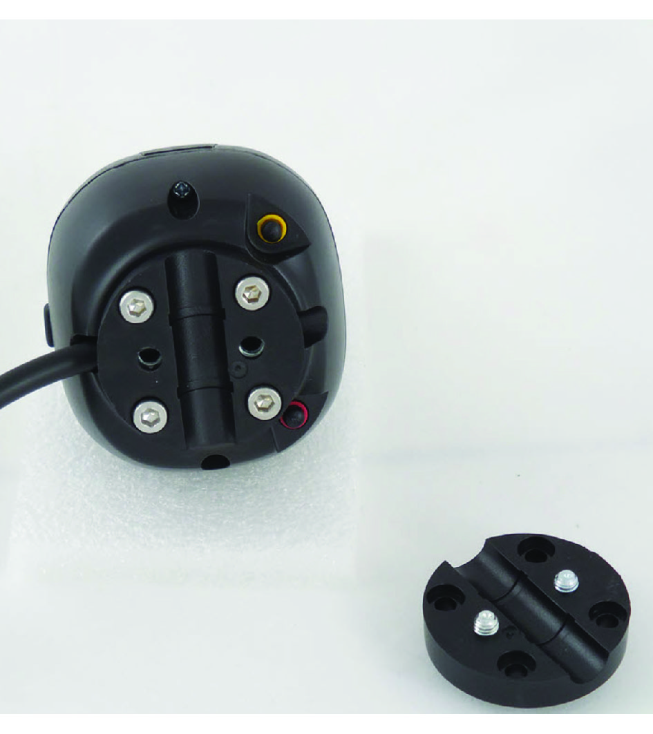
| Place the two M5 locknuts (2) in the first mounting plate. | |
| Secure the mounting plate with the 4 M4 bolts to the base of the joystick housing. | |
Depending on the mounting set, do the following:
|
|
| Secure the second mounting plate with the 2 M5 bolts. |

|
Installation on the power chair
- Place and secure all cabling on the power chair.
- Place a power on/off (pwr) and/or mode (in) switch, secure their cabling and insert their connections.CAUTION: Before inserting a connector, remove the protective cover. If the connections are not used, always put or keep the protective covers in.CAUTION: This is Class I Medical Device (MDR 2017/745). All accessories, including switches, must also comply with the MDR 2017/745 regulations (e.g. the mo-vis Twister, tested according to EN12184 standards).
- Connect the cabling to the wheelchair electronics.CAUTION: All wheelchair electronics must be switched off during installation.